The True
Lead Lag
- Alternating Relay -
Multiple Refrigeration
Control System.
| Home | About Us | Products | Projects | Contact Us | Request For Quote | Search | |
|
The True |
|
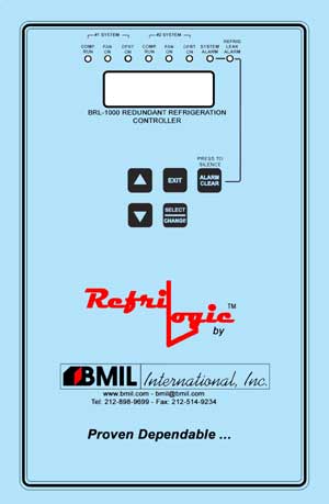
The
RefriLogic
by BMIL
(Lead Lag Evaporator Control System) Specifications:
Download
the
RefriLogic
Menu Manual in Acrobat .PDF format (276KB)
here, 1 Physical 1.1 Enclosure, mounting hardware 1.1.1 8.1” W x 12.4” H x 3.1” D. 1.2 Operating Environment 1.2.1 45°F - 120°F. 30% - 95% relative humidity, non-condensing. 1.3 Membrane – Overlay. 1.3.1 Overlay artwork drafted and is waiting for approval from BMIL. 2 Inputs 2.1 Power 2.1.1 95VAC to 240VAC Universal Power, 50/60 Hz, 2 Amps. 2.2 Temperature Sensor. Qty (1). 2.2.1 Thermistor NTC Sensor with 20 feet cable. 2.3 Inputs 2.3.1 Door Alarm Input. Qty (1). 2.3.1.1 OPEN signal – Door Closed. 2.3.1.2 CLOSED signal – Door Open. 2.3.1.3 Activates a timer when door indicates OPEN. Timer duration is user settable. When timer expires, activate on board Alarm LED, on board Alarm BEEPER, and System Alarm Relays. 2.3.1.4 Auto Clear Alarm when door closed. 2.3.2 Defrost Termination Input. Qty (2). 2.3.2.1 Accepts thermistor NTC sensor with 20 feet cable or Snap-on thermodisc.
2.3.2.2
When System is in defrost, the heater defrost cycle will be terminated
when the Termination Sensor
2.3.2.3 When System is in
refrigeration and the Termination Sensor temperature is higher than its
setpoint or the 2.3.3 FIFO Maximum Cooling Toggle Switch Input. Qty (1).
2.3.3.1
OPEN signal – Use Lead-Lag control method to control two systems. One
system is in primary mode
2.3.3.2
CLOSED signal – Use First-In-First-Out (Round-Robin) method to control the
two compressors on both 2.3.4 Entrapment Input. Qty (1). 2.3.4.1 CLOSED signal – No Entrapment. 2.3.4.2 OPEN signal – Entrapment Alarm Active.
2.3.4.3 Activate on board Alarm LED, on board Alarm BEEPER with faster
tonal pattern, Activate System Alarm 2.3.4.4 Manual Clear Alarm. 2.3.5 Sherlock Leak Sensor Input. Qty (1). Accepts Sherlock CMOS Sensor or Infrared Sensor. 2.4 User Interface, (5) Momentary Micro-Push Buttons. 2.4.1 UP / DOWN – Scroll through menus, sub-menus and to set operating parameters. 2.4.2 SET (Select) – Execute the selected function and to access programming settings. 2.4.3 EXIT - to exit current menu, sub menu and abort any changes. 2.4.4 CLEAR / SILENCE ALARM - to silence and/or clear an active alarm. 3 Outputs 3.1 Relay Outputs. 3.1.1 General 3.1.1.1 Pilot Duty Relay. 3.1.1.1.1 1 Form C, SPDT, 8 amp @ 250VAC Resistive, 6.3 amp @ 250VAC Inductive. 3.1.1.1.2 3.15 Amp fuse in series with common contact. 3.1.1.1.3 Electrical noise suppression device on N.O. contact. 3.1.1.1.4 Visual LED on each relay. 3.1.1.1.5 All outputs utilize screw terminals 3.1.1.2 High amperage relay. 3.1.1.2.1 1 Form A, DPST, 30 amp @ 250VAC Resistive. 3.1.1.2.2 All outputs utilize screw terminals. 3.1.2 Liquid Line Solenoid Relays. Qty (2). 3.1.2.1 Pilot Duty Relay. 3.1.2.2 To Operate LLS valve. 3.1.2.3 Configurable for either NO or NC valve. 3.1.2.4 To OPEN valve when cooling is active. To CLOSE valve when cooling is not active, in Pump Down, in Defrost. 3.1.3 Evaporator Fan Relay. Qty (2). 3.1.3.1 High Amperage Relay. 3.1.3.2 To operate Evaporator Fans Directly. 3.1.3.3 To CLOSE when fan is active. To OPEN when fan is not active, in Defrost, in Fans Start Delay. 3.1.3.4 To activate upon controller activation. 3.1.4 Defrost Relays. Qty (2). 3.1.4.1 High Amperage Relay. 3.1.4.2 To operate Electric Defrost Coils Directly. 3.1.4.3 To CLOSE when in Defrost. To OPEN when not in Defrost. 3.1.5 Alarm Relay. Qty (6). 3.1.5.1 Pilot Duty. 3.1.5.2 System Alarm Relays energized during normal operations. 3.1.5.3 System Alarm Relays de-energized during alarm conditions. Loss of power will indicate an alarm condition. 3.1.5.4 Dry-Contact. 3.1.5.5 Alarm Assignments. 3.1.5.6 Alarm Assignments. 3.1.5.6.1 System Alarm, non-silenceable. Qty (1) 3.1.5.6.2 System Alarm, Silenceable. Qty (1) 3.1.5.6.3 Leak Detection Level 1, Non-Silenceable. Qty(1) 3.1.5.6.4 Leak Detection Level 1, Silenceable. Qty (1) 3.1.5.6.5 Leak Detection Level 2, Non-Silenceable. Qty(1) 3.1.5.6.6 Leak Detection Level 2, Silenceable. Qty (1) 3.2 Communications (Optional). 3.2.1 RS485 hardware and firmware. 3.2.2 “Compak” communication adapter (One per site). 3.2.3 "Gencom" Local / Remote Communications Software. 3.2.4 Modem for Remote Communications (One per site). 4 User Interface - Audio Visual. 4.1 Display. 4.1.1 2 x 16 Characters LCD. 4.1.2 Yellow Back Light. 4.1.3 Indications (Normal Mode). 4.1.3.1 Current Temperature. 4.1.3.2 Current Leak Detection Levels. 4.1.3.3 Current Control Status. 4.2 Status LEDs 4.2.1 System #1 In Primary Mode – Green. 4.2.2 System #2 In Primary Mode – Green. 4.2.3 Liquid Line Solenoid #1 OPEN – Green. 4.2.4 Liquid Line Solenoid #2 OPEN – Green. 4.2.5 System #1 In Defrost – Green. 4.2.6 System #2 In Defrost – Green. 4.2.7 System Alarm – Red. 4.2.8 Refrigerant Leak Alarm – Red. 4.3 Audio Alarm. 4.3.1 Piezo-Electric Buzzer. 4.3.2 90dba at 3ft. 4.3.3 Indicates alarm condition. 5.1 Temperature Control 5.1.1 Controller shall OPEN LLS when temperature is above the Temperature Control Setpoint plus the Temperature Control Differential. 5.1.2 Controller shall CLOSE LLS when temperature is below the Temperature Control Setpoint. 5.2 Fan off and liquid valve closed when door opened. 5.2.1 User selectable option. If enabled, the fan is turned off and liquid valve is closed when door is opened. Minimum fan off time is one minute. If disabled, the door opening does not affect the operation of the fan and the liquid valve. 5.3 Lead Lag Control 5.3.1 Controller shall alternate systems between Lead (Primary) and Lag (Secondary) modes. 5.3.2 Controller will alternate systems when: 5.3.2.1 After temperature within the box is met, the next time a system activates, the previous Secondary system will now become Primary. 5.3.2.2 After two hours of continuous operation without the box temperature being satisfied, units will switch operating modes and activate system alarm. 5.4 FIFO (Round-Robin) Maximum Cooling Control
5.4.1 Use
First-In-First-Out (Round-Robin) method to control the two compressors on
both systems. Both systems 5.5 Programmable Settings 5.5.1 Temperature Setpoint (-45°F - 110°F). 5.5.2 Temperature Differential (0.5°F - 5.0°F). 5.5.3 High Temperature Alarm (-45°F - 110°F). 5.5.4 High Temperature Alarm Delay (2 - 120 minutes). 5.5.5 Low Temperature Alarm (-45°F - 110°F). 5.5.6 Low Temperature Alarm Delay (2 - 120 minutes). 5.5.7 Number of defrosts per day (0 - 6). 5.5.8 Adjustable pump down cycle (0- 240 minutes). 5.5.9 Adjustable defrost time (0 - 240 minutes). 5.5.10 Adjustable drip cycle (0 - 240 minutes). 5.5.11 Adjustable fan off cycle (0 - 240 minutes). 5.5.12 Refrigerant Leak Alarm Setpoint (20 - 999 PPM). 5.5.13 Refrigerant Leak Alarm delay (1 - 120 minutes) 5.6 Sensor Calibration Menu. 5.6.1 Calibrate each Sensor within ±10°F of the raw reading. 5.6.2 Calibrate refrigeration leak sensor. 5.7 Relay Output On/Off Testing Menu. 5.8 Alarm Conditions. 5.8.1 High Temperature for longer than the high alarm delay - Activates Alarm Relay, Buzzer ON, LCD Displays Alarm Message and Output Temperature, Auto Alarm Reset. 5.8.2 Low Temperature for longer than the low alarm delay -Activates Alarm Relay, Buzzer ON, LCD Displays Alarm Message and Output Temperature, Manual Alarm Reset only. 5.8.3 Termination temperature on Termination Sensor is equals to or greater than the termination setpoint for more than 60 minutes, or snap-on thermo disc is closed for more than 60 minutes- Buzzer ON, LCD Displays Alarm Message and Output Temperature, Manual Alarm Reset only. 5.8.4 In Lead-lag control method, one side of the lead-lag system cannot provide enough cooling capacity for over two hours. Buzzer ON, LCD Displays Alarm Message and Output Temperature, Manual Alarm Reset only. 6.1 Designed to meet UL Standard 873. |
Copyright 1996, BMIL International, Inc. All rights reserved
|